Table of Contents
Coypright (C) 2007 Belgabor (main document), The_Cook & Vodhin (as indicated), some rights reserved (see below).
I originally assembled the content of this page with the help of several guys in the original thread. If you have any suggestions, please post them there.
The software tips & links from the thread are on a separate page.
Hi folks,
since I recently started to create custom scenery for RCT3 I think I got a good look at all information about it from a beginner's point of view. My gist is that there is lots of information available, but often hidden deep in (sometimes old) threads whose title do not indicate the wealth of information hidden within. For this reason I start this thread.
This thread is about pieces of information that help creating custom scenery, it is NOT a general custom scenery how-to or tutorial and NOT meant as a place to ask questions (hint: if your question can be phrased as starting with "How do I ..." it does very likely not belong in this thread. The answer though might =) ).
Otherwise if you have information or hints (including errors or things you think should be expressed more clearly in what I've written) you think belong in here, by all means, please post it. I'll try to sum it up and edit this first post to include it.
Note
For all things relating to 3D editing I assume you know the basics.
Personally I use Blender and many things I refer to I found out using it. If things differ in other programs (and I know about it) I'll say so. Please post if you know additional differences so I can keep these things up to date.
Some useful information can also be found in the wiki. It contains some info by jonwil which can't be found here (or at least it's well hidden).
All sizes will be expressed in units (u). This is the unit you find in your 3D modeller (confirmed: 3Dmax, Blender, MilkShape, Sketchup Pro & Demo (1cm), Google Sketchup with Blender Import (1m)).
The newest importer versions allow you to set up a transformation matrix that puts the object correctly for your modeler. To compensate the differences for different modelers I'll define gameplay related axes for the explanations and add a list to which modeler axes they conform.
Table 1. Axes: Definition
| Gameplay Axis | Short | Explanation |
|---|---|---|
| skywards-axis | s-axis | This axis points from down up into the sky |
| main-axis | m-axis | This axis points from the entry into the park. This refers to the main entry you get when you start a sandbox/scenario. |
| across-axis | a-axis | This axis points from the right to the left when you enter the park along the m-axis. |
Here is how these axes map to modeler axes:
Table 2. Axes: Mapping to modeller
| Modeler | Some 3DS/3DSmax versions | Blender and many others | MilkShape |
|---|---|---|---|
| Modeler Coordinate System | Left-handed, y-up | Right-handed, z-up | Right-handed, y-up |
| Importer fixup matrix | none | Fix Orientation | MirrorZ |
| s-axis | y-axis | z-axis | y-axis |
| m-axis | - z-axis | x-axis | z-axis |
| a-axis | x-axis | y-axis | x-axis |
RCT3 tile square: 4 u x 4 u
Walls: 1 u, 2 u and 3 u high for 1/3, 1/2 and full wall respectively. The plain ones seem to be about 0.2 u thick.
Peeps: approx. 1 u, 1.5 u and 2 u for kids, teens and grown-ups respectively.
Coaster rails, Steep Slope: 4 u wide, 8 u high, 8.9443 u long
Coaster rails, Width: Giga Coaster: ~ 1.2 - 1.25 u / Inverted Coaster ~ 1.5 u
Recent reports show that the game might have some problems with very large objects and shadows, so if your object is very large and RCT3 crashes, try to turn off shadows. Custom scenery creators should enable the No Shadows option in the Create OVL window for really large objects.
Note
The scenery is listed by the Size Flag used in the Importer
The +/- u-axis is up/down in RCT3, ie objects 'sit' on the m/a-plane.
Full Tile: the origin is the center of the tile. A full tile cube would be (a: -2 to 2 / m: -2 to 2 / s: 0 to 4).
1/4 Tile: the origin is the center of the quarter tile. A quarter tile cube would be (a: -1 to 1 / m: -1 to 1 / s: 0 to 2).
1/2 Tile: the origin is the center of the half tile. The front of the object is on the +m side, ie the long dimension is along the m-axis.
Wall: Walls span up in the u/m plane. The origin is the middle of the tile edge you place the wall on, the tile being in the -a direction. A normal RCT3 wall therefore seems to be (a: -0.2 to 0 / m: -2 to 2 / s: 0 to 3).
Corner: almost identical to Wall. The difference is how it reacts to the cursor in game. The actual corner of the piece should be at a: 0 / m: 2 to conform to the cursor placement.
Path Edge (inner): Similar to Wall. The origin is inset 0.6 u into the tile (-a direction). Can only be placed on a path/no path edge.
Path Edge (outer): Similar to Wall. The origin is inset 0.2 u into the tile (-a direction). Can only be placed on a path/no path edge.
Path Edge (join): Identical to Path Edge (outer), but can only be placed on a path/path edge.
Path Center: Similar to Full Tile. There are four orientations depending on where on the tile the user places the cursor. That portion will get the +a part of the object. Can only be placed on a path.
Coaster rails, Steep Slope: looking at the slope from the side going up from left to right, the rail the train runs on goes from (in-game) s ~ 0.3 u to 8.3 u. The Angle is 63.4349°.
Here are two diagrams to help you framing tracks of transport or other tracked rides:
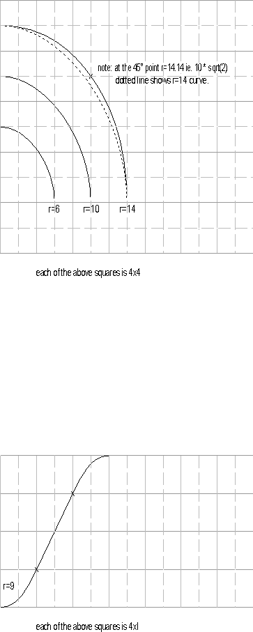
On the upper diagram solid grey lines are RCT3 squares, dashed lines are quarter squares. For the small and medium curves radii are 6 and 10 respectively. For the larger curve the radius starts at 14, but extends to 14.14 at the 45degree mark so that it lines up with the corners.
On the lower diagram the vertical lines are RCT3 squares with dashed lines representing quarter squares and the horizontal lines are 1 u in height, they diagram is stretched vertically in order to make it clearer. The curve of the slope to flat pieces have a radius of 9, the actual slopes themselves rise 2 u in 4 u (1 rct3 square being 4 u).
I hope that this saves you a little bit of effort trying to measure things in-game. These reference diagrams were drawn up after I developed my TrackBeds scenery pack.
First let me explain what unwelding means. When you create a object (example a cube) in a 3D editor, vertices usually are part of multiple faces (ex: a cube has 6 faces (rendered as 12 triangles), 12 edges and 8 vertices, each is part of three faces). Unwelding means that each face gets its own copy of a shared vertex (ex: after completely unwelding our cube has 24 vertices as each vertex gets split into three).
So what does that mean for RCT3? Due to
differences in texture mapping in ASE files and
RCT3 it was necessary to always unweld your
objects, otherwise the texture could be completely screwed up. This is in
general no longer true! The current version of the
Importer perfectly understand welded
objects.
“Why is this still an issue?” you may ask. Let's have a look:
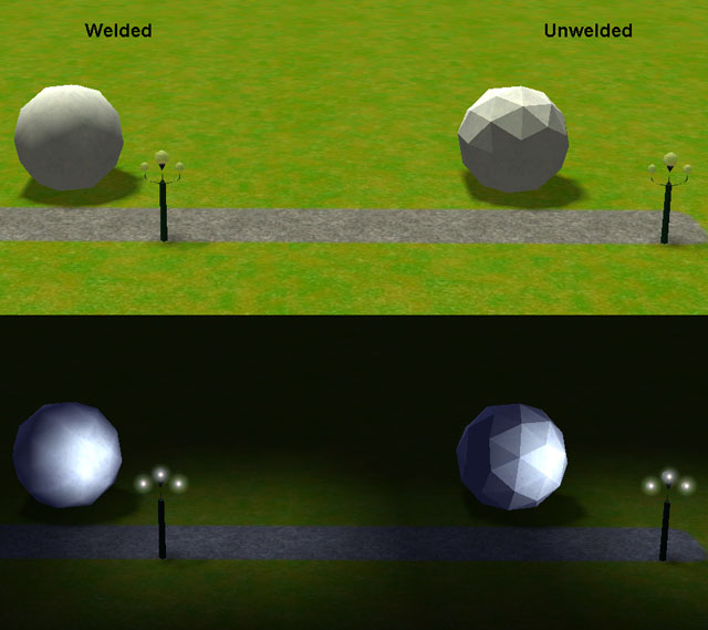
As you can plainly see, unwelding is a bad idea (besides that some rendering calculations are done on a per-vertex base so unwelding increases rendering time), or is it? Let's have another look at a different object:
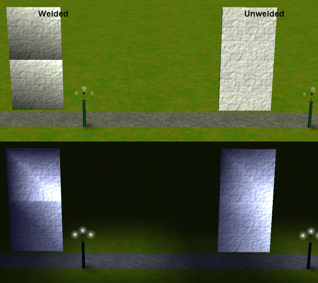
Now the unwelded version looks much better.
If you think a bit about it, maybe you already grasp whats going on from these pictures.
In the meantime I'll continue to explain ;-)
As you can see, the remaining issues are with lighting. Lighting is done by the vertex normals. So lets have a look at the normals before and after unwelding:
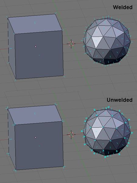
What the normals in the unwelded case do is to simulate a rounded corner by lighting (look how the vertex normals are the mean between the face normals), this is lost when you unweld as each vertex now has the normal of its face (still the mean, but it's only attached to one ). Therefore in the first case unwelding leads to the flattened appearance. In the second picture in the welded case the engine tries to give the corners of a cube a rounded look which looks like utter crap. Therefore:
Important
In current versions of the Importer: keep rounded corners welded, unweld pointy corners.
A few tricks I found regarding this:
You can also partly unweld vertices if they are at a flat/rounded interface.
If such an interface is at the end of an object (eg a rounded corner piece that could continue to a straight wall) make sure the rounded part ends with a (slim) poly that is parallel to the straight wall. This leads to the vertex normals that border to the straight wall to be orthogonal to it (artificially “welding” these vertices with the adjacent straight wall's vertices). If you don't do that, the edge between the rounded corner and the straight wall will be visible.
Inner vertices on a flat multi-poly surface can and should be welded.
Blender Users: Try the EdgeSplit modifier in the latest experimental builds (see Automatic Unwelding). It automatically implements my recommendation.
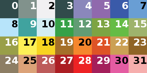
Vodhin discovered that (former) Unknowns 3-5 actually represent default colors for recolorable objects. The following scheme shows which number represents which color:
I did some research using a table generated from jonwil's published sid files (349 objects). I'll write things I deduct from this in emphasized.
Fl1: No idea. Seems to be randomly set or not.
Fl2: Never set
Fl3: Set a few times, always with Fl1, Fl4, Fl7, Fl8, Fl33 and Fl34. If set, Fl2, Fl10-Fl32, Fl35 and Fl45-Fl64 were never set.
Fl4: Set if either Fl3 is set or the Scenery Type is Stall
Fl5: If set, object is deleted when altering the ground. Never set
Fl6: If set, object doesn't move with the terrain (Fl33 unset) or terrain cannot be modified under it (Fl33 set). Never set
Fl7: Set on non-path objects, unset on path objects and path objects acting as general scenery (eg lamps to place on terrain). Exception: unset on Pizza Stall (buggy sid?).
Fl8: Not really sure. Set on all stalls, park entrances, fountains and when Fl3 is set, but also on a very few others.
Fl9: If set with Fl33, the object blocks supports (ie they stop above). With one exception only set on the terrain blocks.
Fl10-Fl12: Never set
Fl13: Object skews with slope (like fences do). There has to be more to it as it is set on a lot of objects that do not skew in game.
Fl14: Object moves up/down smoothly, it doesn't jump in set increments. Probably confirmed. Fl13 is always set if this is.
Fl15-Fl23: Never set
Fl24: Set only for fences (also for fence-like objects from other Scenery Types).
Fl25: Never set
Fl26: Places the object among the billboards. Set on billboards.
Fl27-Fl32: Never set
Fl33: If unset, object is invisible to the game (no collision checks). Set on almost all objects.
Fl34: If set, the object removes path supports. It may be necessary to set (all?) unknowns to 0 for this to work. Set on almost all objects. Fl33 and Fl34 are always either both set or not.
Fl35: Never set
Fl36: No idea. Set on all Flowers, Stalls and Terrain Pieces but also on several other objects.
Fl37: No idea. Set without obvious pattern on about half the objects.
Fl38: No idea. Set on all Flowers, Stalls and Terrain Pieces but also on several other objects.
Fl39: No idea. Set on all Flowers, Stalls and Terrain Pieces but also on several other objects.
Fl40: No idea. Set on all Benches, Flowers, Stalls and Terrain Pieces but also on several other objects.
Fl41: No idea. Set on all Flowers, Park Entrances, Stalls and Terrain Pieces but also on several other objects.
Fl42: No idea. Set on all Flowers, Park Entrances and most Stalls but also on several other objects.
Fl43: No idea. Set on all Benches, Flowers, Park Entrances and most Stalls but also on several other objects.
Fl44: No idea. Set on all Flowers, Park Entrances and most Stalls but also on several other objects.
Fl45-Fl64: Never set
Note
Fl36-Fl44: They seem to be related, but I found no obvious pattern. The stalls that are not 'most' are often the generic stalls. The Pizza stand has none of these flags set (I start to believe that this sid is broken).
There is a thread by jonwil where he reports in what circumstances some flags are checked in-game.
Important
I will now use the new (since Importer v17) values for Unknown1 and Unknown2.
Uk1, Uk7 and Uk8: Those seem to manage collision detection and probably only matter if Fl33/34 are set. They seem to work in conjunction with Size and/or Size in Squares.
Uk1 = 0 means RCT3 should figure out collision for the item from the model's 3D data. An example for this in action are the diagonal dinosaurs which only block the space they actually take up. Usually Uk7 is 0 and Ek8 is deactivated in this case.
Uk>1 gives RCT3 the height of the collision box for the item in modeller units. In this case Uk7 = Uk1 and Uk8 = 2Uk1-1. I cannot be sure, but guess this is easier for the engine to calculate and causes less lag when placing items with collision detection.
Uk2: Either 0 or 2. All Trees and most Walls have 0. All Stalls have 2.
Uk6: This was reported to set the height in units to determine collision detection. Seems doubtful as it is mostly 0. See Uk1.
Uk7: See Uk1 (I found a post mentioning that setting Uk7 is enough, so far untested by me, but I don't think it is enough as the poster reported some errors later). Usually if this is 0, Uk8 is disabled.
Uk8: See Uk1
Uk9: Always 1
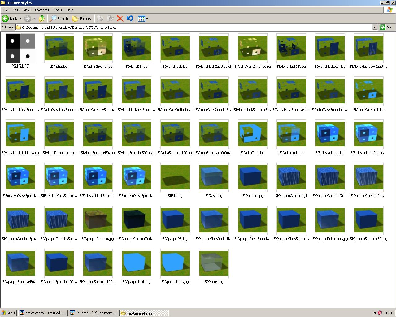
The texture types are almost self explanatory: ([] = a part of a name)
| ||
| --Vodhin, Belgabor | ||
Iceatcs created a picture that shows off the different options:
 This work is licensed under a Creative
Commons Attribution-NonCommercial-NoDerivs 3.0 License.
This work is licensed under a Creative
Commons Attribution-NonCommercial-NoDerivs 3.0 License.The DocBook CSS used for the HTML version of this document is based upon the one created by Chris Karakas.
This CSS stylesheet uses QBullets in links. Thanks to Matterform Media for providing QBullets for free. If you plan to use them on your website, please observe the QBullets usage terms.